PRODUCT ENGINEERING-MANUFACTURING
COMPANY: SIEMENS
DIVISION: Energy and Automation
SEGMENT: Custom Controls
SERVICE: Manufacture "Customized" Control Panels
CUSTOMERS: Husky Plastics - Tokyo Electron
DATE: 1993-1996

PRODUCT: Electrical Switchgear design
Position: Electrical Designer
I received schematics from our customer.
Each being a customized unit. I Designed a method for customizing layouts in AutoCAD Lt.
I perfomed Full Design Cycle of "Custom" "Mutli-Bay" Control panels.
I created the manufacturing documentation for assembly. Provided customer and manufacturing support. Tracked project quality and improvements.
Redrew the schematics in "E-Plan" or "Promis-E" to extract wire data.
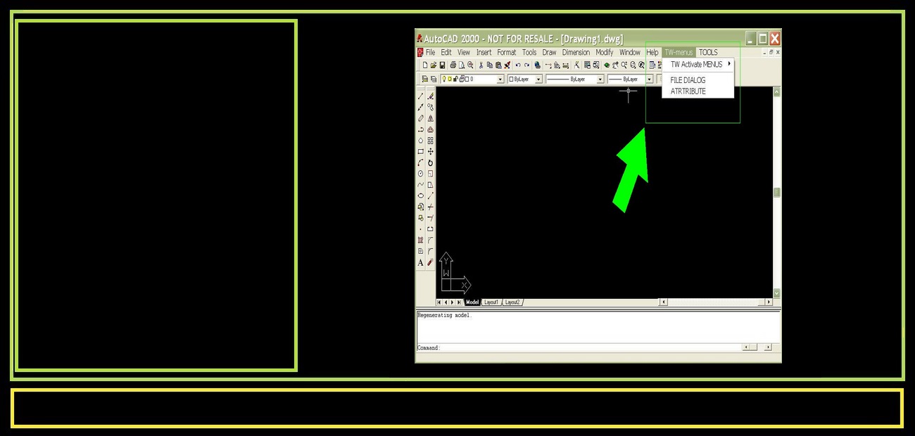
In order to Simplfy design,I customized the Autocad menu system.
Automated prompting of device IDs. Making all components and structures to scale. Building the Assembly Instructions "around the models".
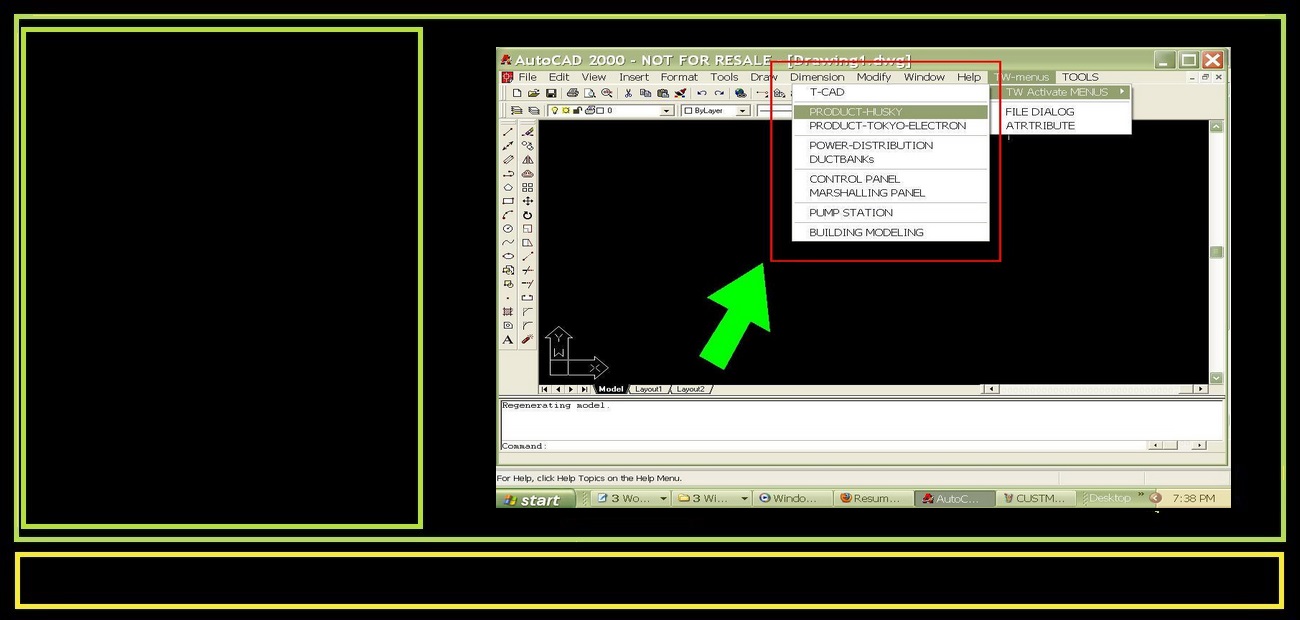
Other engineers could now design using my system.
This increased productivity and simplyfied engineering design. With no need to train engineers in CAD. We increased From 1-3 units to 5-7 units and 1 "special" large unit per week, often more than 300 components per unit.
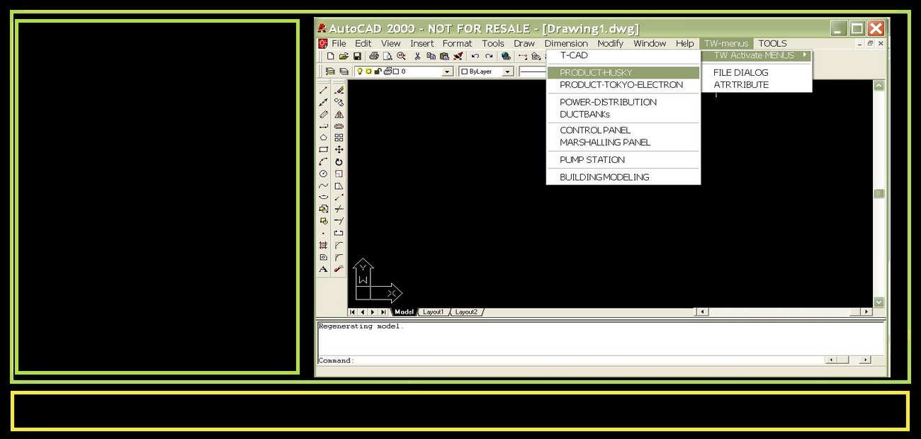
Then by modularization and standardization of designs, Engineers were able to simply copy and modify, similar designed customized units by using my matrix of existing designs. This increased quality and standards. I did this for two major projects."Husky Plastics and Tokyo Electron".
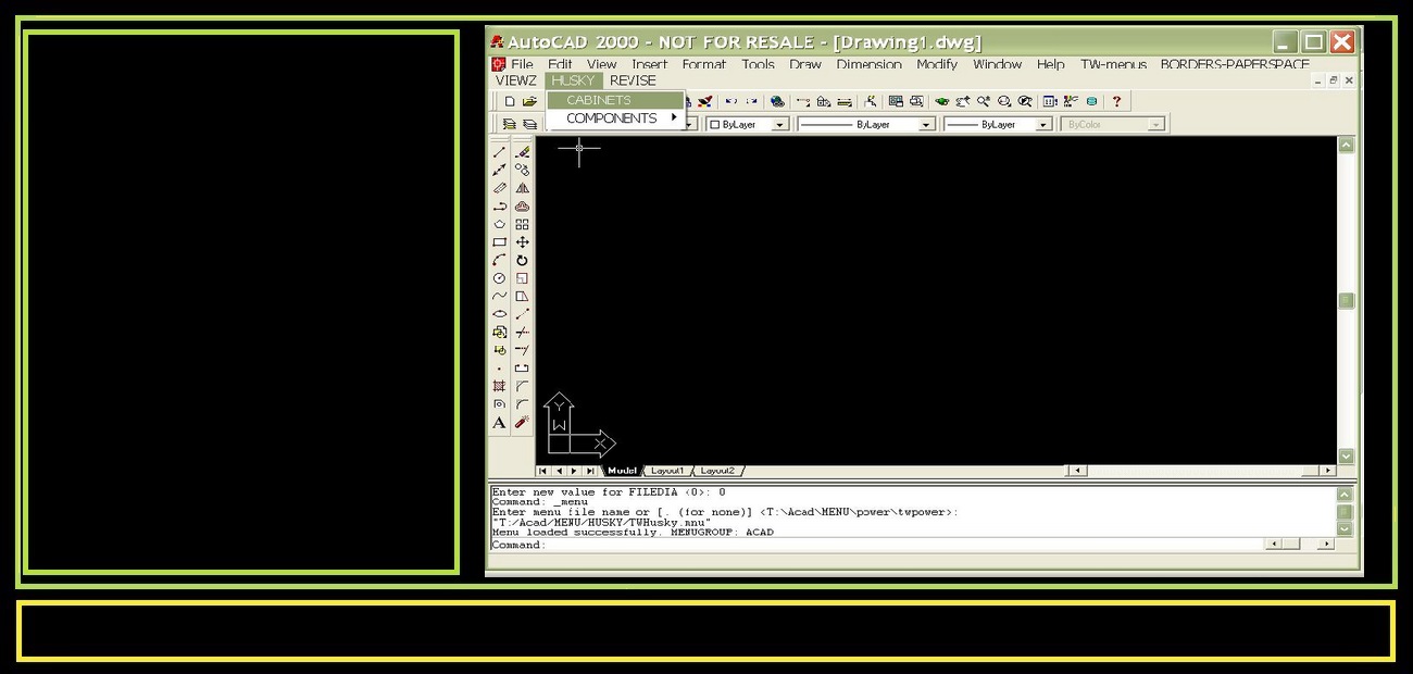
"1st step" was to select the appropriate size cabinet for layout. Control panels were "multi bay" with up to 6-7 bays. Dependent on design may include false bases or plinths for cable entry. These machines were "custom but not simple".
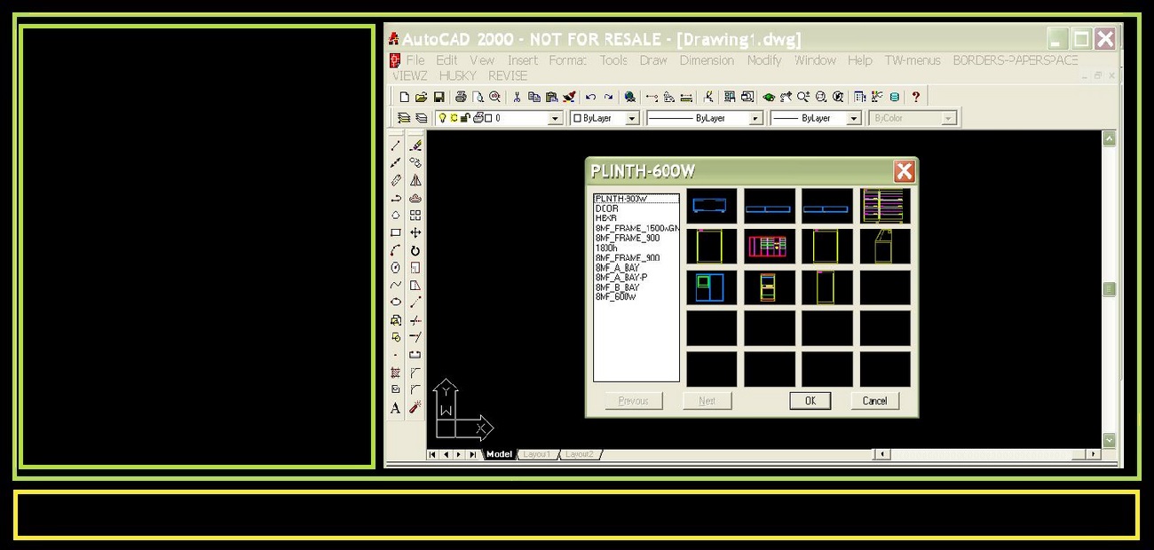
The menu shown on right shows the "Icon menu" I programmed to physically pick cabinet bays and supports needed for layout.
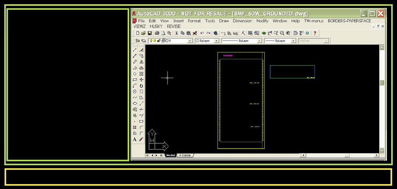
Next was the selection of various size mounting panels for equipment and placement in the cabinet rear or sides. Door mounted components were done later and last.
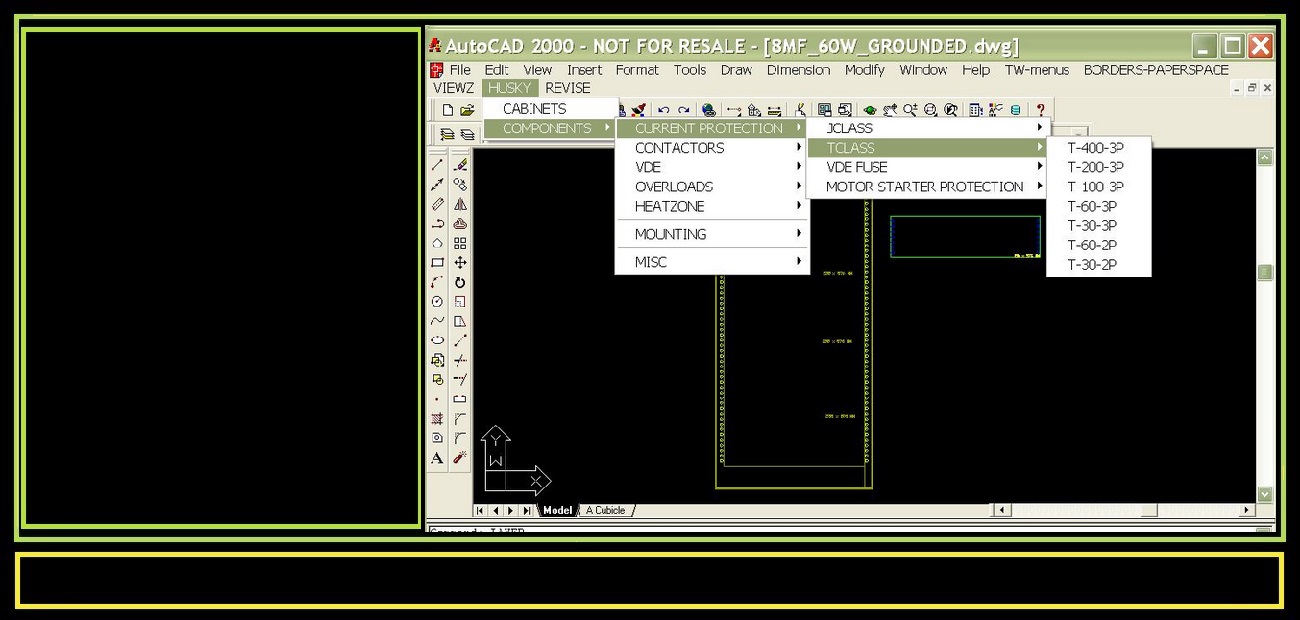
Next was the selection of components to be mounted. Current protection, transformers, fuses, relays, etc. All based on US or European class standard (VDE) for particular machines.
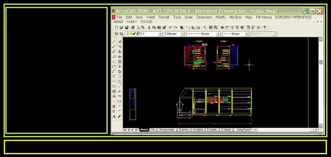
By following the menu system in sequence, eventually the user would design all panels for all enclosures to include a front and rear side of a "swing frame" in the machine - (typically central). This completed the design in "model space" to scale 1 to 1, to assure fit and function.
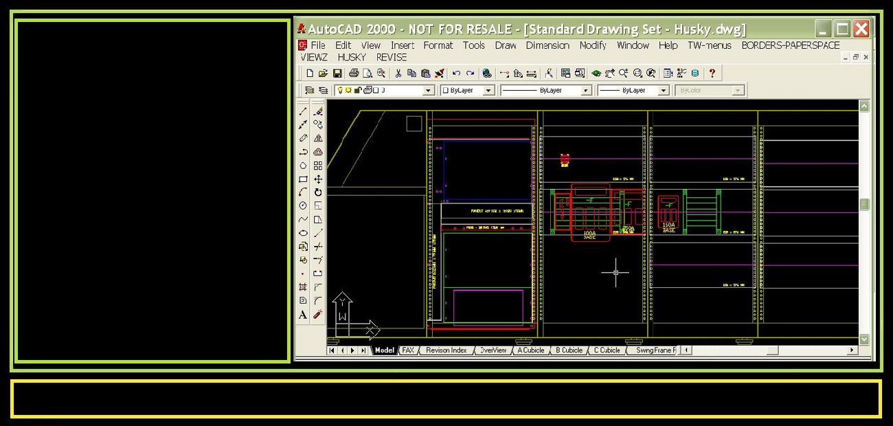
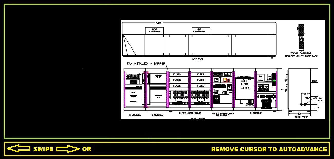
Here is a Mutile bay "Switchgear". This is a typical 5 bay panel (incomplete) but control panels may have as many as 7 bays, including cable connectors on the rear and a control operator station.
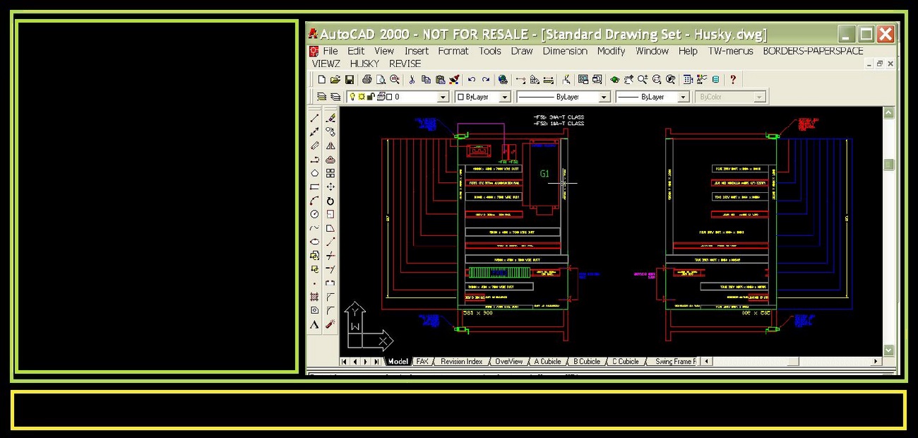
This is a typical "Swing frame"- designed to be able to swing open for access to both sides of panel for repairs. "Modularly" the place where heat relays were placed common to all units, thus panels were standardized in design and standarized as far as most controls general placement.
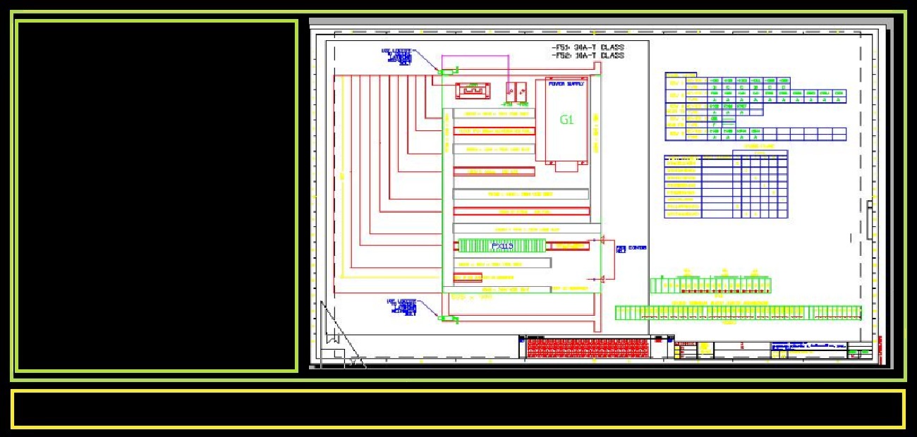
With all components designed in model space,- paper space was used to superimpose assembly directions on top of the design. This included wire duct lengths and placement, cable lengths, mutilple component id's and jumpers, thus the entire panel was encapsulated into a single drawing.
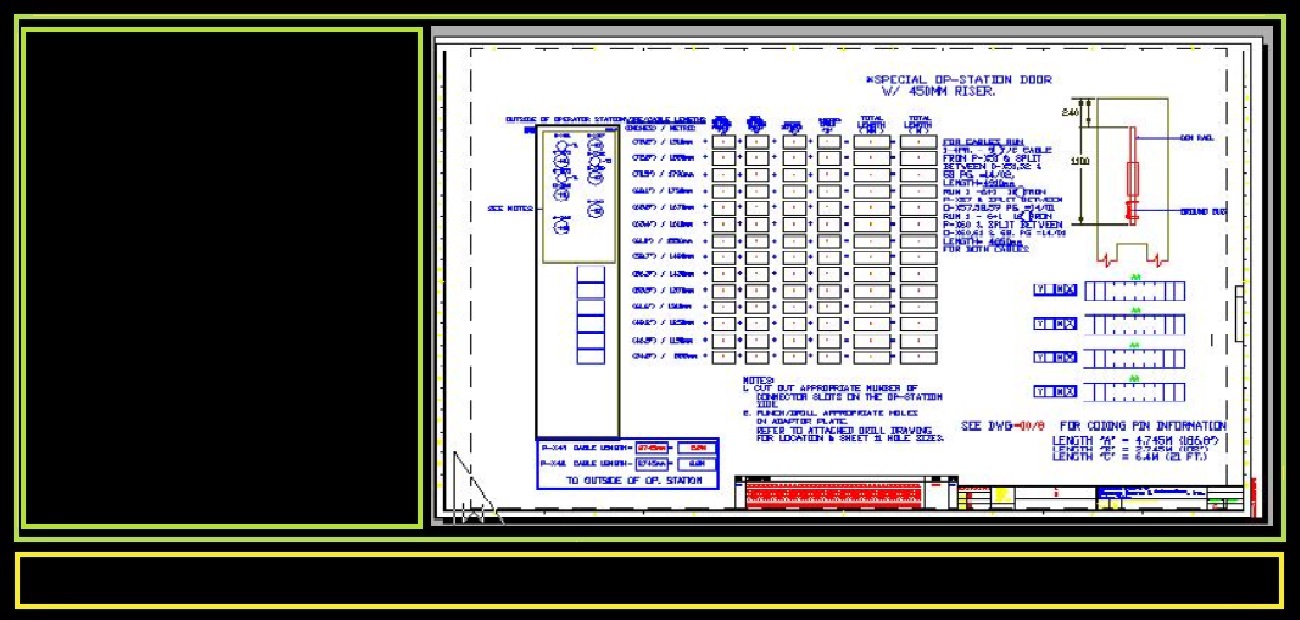
On the right is the "operator station" showing a special panel cutout at top for Hubble connectors. On the right shows an Addition matrix to determine cable lengths needed to run back to machine as well as terminal block jumpers.

I created tools and standardized production, as well as, supported manufacturing and addressed customer quality concerns. This was my contribution to revolutionizing production. Had I been given Full Autocad, I would have extracted BOM's and streamlined the ordering process, simplifiying manufacturing further. (On the right customer showed appreciationto my efforts.-1000th panel manufactured.)


